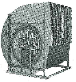
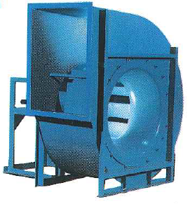
Airfoil FANS are available in the following sizes, wheel designs, and air & pressure ranges.
| Sizes | Wheel Designs | Air Volume & Static Pressures |
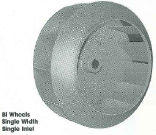
| 245-1200 | BI - Backward Inclined Blades | To 186,000 CFM & 16" W.G. |
365-1200 |
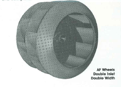
AF - Airfoil Blades | To 188,000 CFM & 16" W.G. |
1320-2175 |
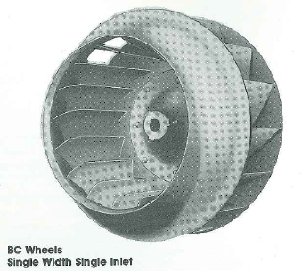
BC - Backward Curved Blades | To 710,000 CFM & 16" W.G. |
Aerodynamic features include non-overloading horsepower characteristics and high efficiency.
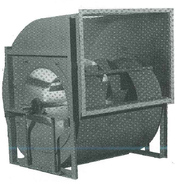
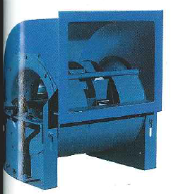
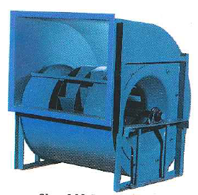
WHEELS
BI wheels, including blades, wheel flange and backplate, are made of high-strength steels as standard. Blades are welded to the spun wheel flange and backplate.
AF wheels, including blades, wheel flange and backplate, are also made of high-strength steels as standard. Blades are die-formed and welded to the spun wheel flange and backplate.
BC wheels are made of die-formed, high-strength steel blades, die-formed steel flange and steel backplate as standard. Blades are welded to wheel flange and backplate.
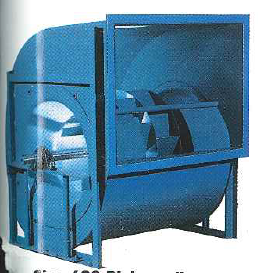
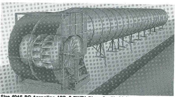
Bl and AF double-width, double inlet wheels utilize a common centerplate wheel design. BC double-width, double-inlet fans utilize two BC wheels.
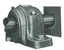
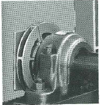
All Airfoil fan wheels are offered with cast iron hubs. Hubs are designed with a high hub-to-wheel ratio which adds to the overall structural integrity of the wheel. Hubs are straight bored to a close tolerance fit to the shaft. Wheel/hub assemblies are keyed and set screwed to lock the wheel to the fan shaft.
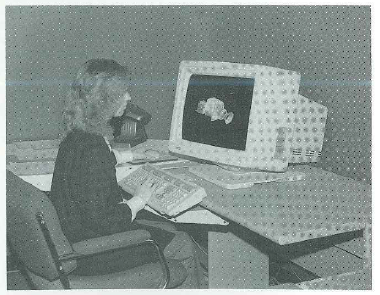
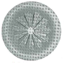
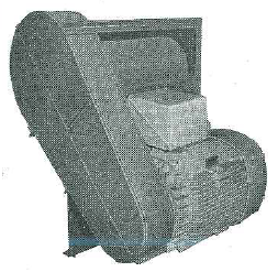
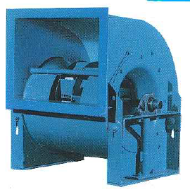
State-of-the-art CAD tools are used to design and detail the entire fan line. Multi-light source shading of a 3-D model is shown.