"L" Series HEAVY DUTY
CONSTRUCTION FEATURES
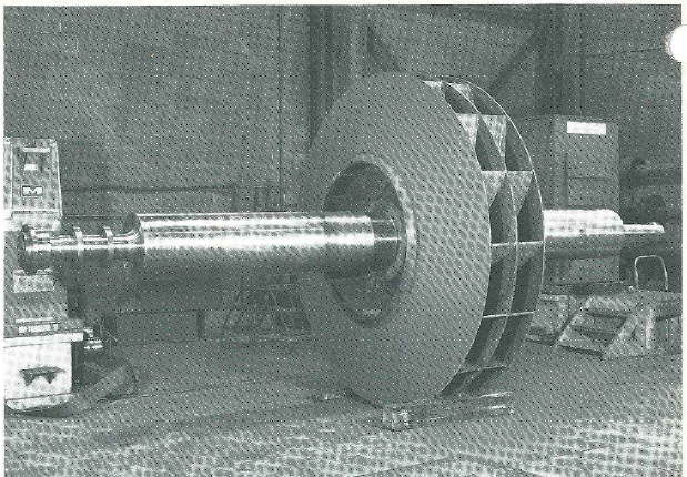
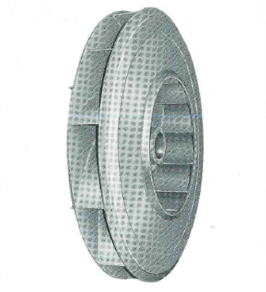
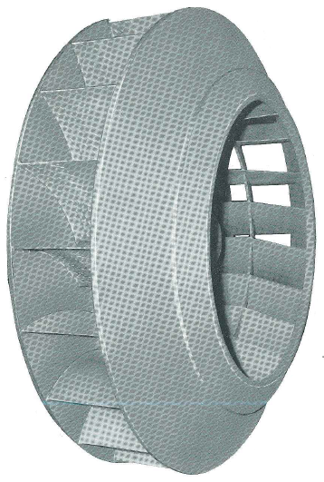
WHEELS
The “L” Series consists of 6 aerodynamically related wheel designs each available in 14 wheel diameters.
In the original design and manufacture of these wheels, blade and flange stresses were first calculated according to accepted engineering practices. These values were then verified: SR-4 strain gauges were located at critical points on the wheel and wire leads connected to amplifiers, recording equipment and oscilloscope. Stresses were checked by spin tests in evacuated test pits ending in destructive failure of the wheel. These tests validated the fact that operating wheel stresses were well below the yield strength of the steel used.
Fan wheels are now designed using sophisticated analytical techniques such as finite element analysis, modal analysis and fatigue analysis to assure the mechanical integrity of the wheel.
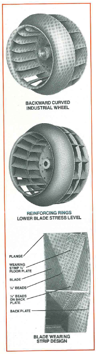
When necessary to lower the blade stress level, the reinforcing rings at blade heel and/or blade tip are used.
During manufacture of “L” Series wheels, constant, detailed inspections are made of all component parts and assembly welding. Welding is constantly supervised and inspected, with inspection tools such as dye penetrant, magnetic particle inspection, and Radiography (X-Ray). Each design of wheel has been subjected to resonant vibration tests and dampening features added where necessary. All wheels are statically and dynamically balanced to assure smooth operation.
Service records extending over many years are further assurance of satisfaction for both operating and maintenance personnel.
SHAFTS
The “L” Series shafts are as carefully designed as other component parts. Stresses and deflections on every order are checked to assure that critical speeds are well above operating speeds.
"” furnishes shafts of two types.
1. Shafts up to 7%" in diameter are hot rolled steel. Fans arranged for sleeve bearings have thrust collars either integral with the shaft or are fitted and pinned to the shaft, then ground to assure correct fit with the bearings. On fans utilizing high thrust RT bearings thrust collars are split and fit into a machined shaft groove. These thrust collars provide correct axial location of the wheel on single and double width fans in addition to absorbing the thrust on single width fans.
2. Fan shafts 8" in diameter and larger are turned from forgings. After the initial heat treatment during forging, the shaft is tem-pered, normalized and heat-treated to relieve locked-in stresses in preparation for machining.
All shafts are carefully turned and ground to very close tolerances, keyways are carefully cut and the keys fitted to the shaft with the wheel in place.
The shafts are then inspected, and either sent to the assembly department for fans shipped fully assembled, or protected with a corrosion resistant coating, wrapped and boxed for shipment for fans to be field- assembled. On some larger “L” Series fans, for special applications, the wheel is shrunk on the shaft and the entire assembly is shipped on a special cradle.
ABRASION RESISTANT WHEELS
On induced draft applications, where wear is anticipated, offers a wear strip and weld bead combination. This consists of a strip of thick, cross-hatched hardened floor plate welded to the blade at the centerplate or backplate and built up at the edges with weld beads. The inertia of the dust particles carries them toward the backplate or centerplate where the wear plate at this section withstands most of the abrasion normally affecting the blade. The weld beads are angled along the edge of the wear plate and break up particle flow to prevent impingement and scouring.
Wear plates can also be provided for the backplate or centerplate as well as wider wear plates for the blades for application with high particulate loading.
On those applications where the dust concentration is high and particles are very abrasive, wear plates of special hardened steel or with special overlays can also be furnished to increase the service life of the wear protection.
"L" Series HEAVY DUTY
CONSTRUCTION FEATURES
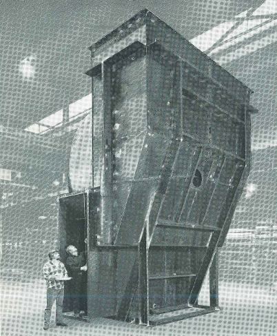
SIZE 2640 L-21 SINGLE WIDTH HOUSING WITH INLET BOX
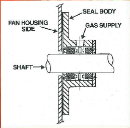
SHAFT SEALS
All “L” Series fans are equipped with a split seal consisting of two sheets of woven high temperature fiberglass held between split steel plates. The seal is adjustable for a close fit to the fan shaft to minimize leakage around the shaft where it passes through the housing or inlet box.
For gas tight construction, carbon ring and labyrinth designs are available. To prevent any leakage of contaminant outward, these seals are usually pressurized; other mechanical seals and stuffing boxes are also available.
HOUSING AND INLET BOXES
Each “" “IT Series fan has a specific housing design to provide the best performance in combination with the wheel. Dimensions are selected for streamlined design to provide smooth gas flow. The large housing outlet allows gradually diverging airflow, which reduces turbulence to a minimum; and obtains the highest static pressure conversion. This streamlined flow increases static efficiency and reduces housing wear. Due to the diverging airflow at the fan outlet, losses in the system beyond the fan are lowered and abrasion is reduced to a minimum.
Inlet boxes, made for the specific “IT Series fan, are adequately sized to assure low entrance loss and smooth air flow. They are tapered to guide air efficiently into the fan inlet.
The housing and inlet boxes are made of heavy commercial grade A36 steel plate continuously welded with generous bracing of heavy rigid structural shapes to prevent breathing and vibration.
The housing is provided with a flanged outlet on all “IT Series fans and flanged inlets on all inlet boxes, and on the inlet on arrangement 1 fans if an inlet box is not required.
Most “IT Series fans are provided with split sections in the housing and inlet boxes for rotor and shaft removal without disturbing duct connections. These joints are usually gasketed with woven fiberglass and bolted on close centers. On large units, which require additional splits for shipment, a field welded joint is used.
Where inlet boxes are shipped separately to facilitate shipment, these units are provided with alignment clips to locate the inlet boxes prior to customer’s final field welding.
During factory fabrication, the housing, inlet bells, and inlet boxes and dampers are erected as a unit. All sections are carefully aligned, consistently inspected for dimensional accuracy and quality of workmanship, and match-marked, before dismantling for shipment.
"L" Series HEAVY DUTY
CAPABILITIES
PLANT FACILITIES
offers plant facilities and know-how specifically suited to the design and manufacture of Heavy Duty Fans unmatched in the air handling industry. This factory backup, coupled with the resident sales engineers assures you of rugged quality construction that will be properly applied and give you many years of trouble-free service.
RESEARCH FACILITIES
The Research Department is staffed with personnel who represent years of experience in fan research, development, and testing. This staff is backed up by a complete laboratory facility for research and development testing including a 2000 HP variable speed unit for performance, overspeed and strain gauge testing and computer facilities to aid in data analysis.
The Research Laboratory is equipped to conduct performance tests in strict accordance with either AMCA or ASME Fan Test Codes and is also equipped to conduct sound power level tests according to the AMCA Sound Test Code.
is a pioneer in fan noise research and was one of the first fan companies to publish reliable fan noise data. The Research Department has published several important technical papers on this subject and has contributed considerable technical information to both AMCA and ASHRAE that was used to formulate the noise test codes of both organizations.
As a result of this extensive experience, can supply accurate, reliable sound data on all Fan Designs.
Ever increasing demands on fan equipment has resulted in larger and higher speed wheels resulting in highly stressed components. Research is equipped with complete strain gage facilities to investigate and analyze both stress and vibration under operating conditions and has conducted extensive tests in both the laboratory and the field on vibration pat-terns and resonant frequency problems. Finite analysis or Modal analysis tech-niques are regularly employed. In some cases, prototype wheels are run to destruction in a special vacuum spin pit to verify predicted failure speeds.
Results of these testing programs are combined with the accumulated experience and knowledge of the Research Department to produce efficient reliable fan designs to meet today’s requirements.
MANUFACTURING FACILITIES
continuing capital expenditure program includes new plants, expanded facilities, subsidiary acquisitions, new tape controlled machines and sheet metal shop tools as well as an expansion in qualified personnel.
Manufacturing at is geared to provide the most accurate control and up-to-date methods for Heavy Duty Fan manufacture and delivery available in the industry. "” has designed and built heavy machinery such as billet shears, iron working machines, bending rolls and huge process machinery for many years, and the manufacturing and design experience thus gained is constantly applied to Heavy Duty Fan manufacturing. In addition, has large capacity presses, welding fixtures and machines, shaft grinders, turning lathes, vertical and horizontal boring mills, a pit furnace and balancing machines, all necessary to make Heavy Duty Fans a product that is completely manu-factured under “one roof” with resulting control of quality and delivery. This unique combination of physical facilities and expe-rienced personnel makes “'s” qual-ifications for Heavy Duty Fan manufacture unequalled in the air handling industry.
QUALITY CONTROL FACILITIES
The quality level maintained by in the manufacture of Heavy Duty Fans has resulted in a reputation for long service life. Experienced engineers administer the Quality Control System at , and the Quality Control Manager holds an in-dependent management position, assuring objective decision-making concerning product quality.
Quality Control inspectors are an integral part of each department where Heavy Duty Fan components are made, and no part or product leaves these departments without quality verification made from written Quality Control records of component manufacture. Welding procedures are
completely documented and are closely controlled and supervised. Weld passes are subjected to visual testing including dyepenetrant and magnetic particle inspection, and where required, Radiog-raphy (X-Ray) is used to assure the highest quality welded assembly.
Quality Control maintains a materials laboratory to verify quality level of materials used in component manufacture. The lab is equipped with modern testing equipment, including spectrographic analyzers and tensile testing machines, and is staffed with experienced technicians.
All Heavy Duty Fans are mechanically tested by welltrained experienced, test inspectors under the direction and supervision of Quality Control, utilizing modern vibration analyzing instrumentation. Fans shipped completely assembled have all operating components thoroughly checked at this running test, and rotors for fans shipped knocked-down for field assembly are tested with sensitive vibration instru-mentation on large, modern balancing machines. This testing assures a trouble free startup of Heavy Duty Fans when properly erected and aligned.
- "H" Wheel undergoing Shaker Frequentcy analysis
- Size 2520 A-1660 Wheel in stress relief and shrink fit furnace.
- 140" Wheel in overspeed test facillity, witch can accomodate 190" diameter wheels.
- Full scale fan testing facillity
- Test labaratories utilize computer controlled data acquisition systems that sample all variables and calculate find results in "real time" enabling design engineers to make on-the-spot refinements.
- 2520 Airfoil Wheel in large balancing machine for static and dynamic balance.
- Modal analysis is used to insure that vibration characteristics, such as natural frequencies, mode shapes and damping factors, meet design criteria.
ENERGY EFFICIENCY
Energy efficiency has become an increasingly important factor in the selection of mechanical equipment during the last decade. This is particularly true in the case of fans applied to industrial service which must be designed to be both energy efficient and be able to withstand the rugged operating conditions imposed by various industrial processes. These conditions fre-quently subject fans to abrasive wear and/or material build up due to the fan having to handle large volumes of particulate matter. The problems associated with abrasive wear include reduction in fan performance and eventual rotor failure (possibly of a catastrophic nature) due to the lack of structural integrity from loss of material. The problem associated with material build up on fan rotors appears as unbalance of the rotor as portions of the build up are dislodged from the rotor, often necessitating shutdown of the equipment for the purpose of cleaning. To meet the challenges of this rugged industrial service, engineers have developed a new series of energy efficient fans for handling dirty, dust laden gasses - the "D" series fans.
LOW ABRASION
The "D" series fans combine the energy efficiency of a backward curved fan wheel with the lower abrasion characteristics and decreased build up tendencies of our unique rotor and housing geometry.
This provides a superior product for handling dust laden gasses. Its ability has been demonstrated in operating tests of the "D" fan versus a radial bladed impeller in the same fan housing handling identical particulate matter for actual industrial appli-cations. One specific test involved a "D" fan versus a radial bladed fan equipped with identical wear protective devices handling large volumes of petroleum coke. The radial bladed wheel in this test originally weighed 874 lbs. The wheel was replaced after 2681 hours of operation at which time it weighed 840 lbs. before cleaning and 800 lbs. after cleaning. Therefore, the severely eroded radial bladed fan lost 74 lbs. of material due to wear and had 40 lbs. of petroleum coke build up after handling 7032 tons of petroleum coke (60gr/ACFM). This works out to .0105 lbs. of material loss per ton of petroleum coke handled.
The "D" fan wheel in this same test weighed 936.5 lbs. when new. This wheel was replaced after 3092 hours of operation at which time it weighed 900 lbs. This wheel was not worn as severely as the radial bladed wheel but it was decided to replace it.
Therefore, the "D" fan wheel lost 36.5 lbs. of material due to wear after handling 6332 tons of petroleum
coke (51 gr/ACFM). This works out to .0057 lbs. of material loss per ton of petroleum coke handled.
The "D” wheel, under the actual operating conditions of this test, proved to wear at almost half the rate of the radial bladed wheel when compared on the basis of handling equal volumes of material. But that's only one part of the "D" fan story. During this same period, the radial bladed wheel required 99 Kw to operate at full production while the "D" wheel required only 84Kw as measured by in-place recording equipment. This is an energy savings of 15% over the lifetime of the equipment.
While the test described above is an industrial application that is more severe than most, it proves that the "D" fan can handle the most severe of industrial applications and save valuable energy in the process. The "D" fan has also been applied to other industrial dust-laden applications including cement kilns, utility boilers, lime kilns, municipal solid waste boilers and many others.
feels that the "D" fan is the fan you should be considering for all industrial applications handling dirty, dust-laden gasses.
CAPABILITIES
can proviae the "D" fan with various wear protection devices to extend the life of the equipment as well as simplify repair of the equipment when wear occurs. can provide blade and back- plate wearplates of standard steel as well as special wear resistant materials such as raised pattern fourway diamond steels, quenched and tempered steels, abrasion resistant steels, hand applied welded hard- facing, chrome carbide hardfaced plate and plasma sprayed coatings. Fan housing scroll and side liners of these materials are also available. design engineers can also design the mechanical structure of "D" fans to improve the maintainability of the equipment. Features such as all-welded- hub-to-backplate/ centerplate connection (no fasteners to wear), removable flanges for narrow wheels, wheel stiffening ring covers and spray nozzles improve the availability and reliability of equipment as well as maintainability. designers are experts at handling difficult industrial applications - let us help you with yours.
The "D” wheel can also be retrofit into existing radial tip fan housings, meaning that users of existing fans can also take advantage of the energy saving characteristics of the "D" fans. Whether your industrial application involves complete new fans or modifications to existing fans, the "D" fan provides improved efficiency, extended wear life and resistance to material build up.
Call your local Sales Engineer for a proposal on the "D" fan for your application.
INTRODUCTION
Heavy Industries and Utilities with severe operating conditions have looked to for dependable rugged fans based upon performance and operating experience for over a century.
From this experience has evolved a related line of heavy duty fans in standard and special designs of nearly every available material.
Series H-12,
H-14, H-16, H-20, H-26 and H-36 are each available in 14 basic sizes for pressures to 100 inches.
Capacities range from 1050 to 920,000 CFM to cover a wide range of applications.
The series “H” fan was designed for rugged industrial and power plant service, with combined features that make “H” fans an ideal selection for almost any induced draft application involving dirty or high temperature gas, or both. In addition, a sharply rising pressure curve gives the “H” fan excellent characteristics for parallel fan operation or any application where stability is important.
In the original design and manufacture of the “H” Series “prototype” wheels, blade and flange stresses were first computed according to the latest engineering practices. These prototype wheels were then subjected to strain gauge tests at critical points on the wheel to verify computed stress. The proto-type wheels were then subjected to monitored spin tests to failure in a vacuum spin pit to verify previous testing. These tests assured that the “H” Series wheel design has conservative operating stresses well below the yield point of the materials used.
Fan wheels are now designed using sophisticated analytical techniques such as finite element analysis, modal
analysis and fatigue analysis to assure the mechanical integrity of the wheel. Of equal importance is the correct selection and application of Heavy Duty Fans, (the best fan improperly applied can be a costly experience to any user). For this reason, has established qualified graduate engineers as resident sales representatives in your area. These men have received several years of specialized inplant training, updated regularly by in-plant training sessions, plus extensive experience in the field. With this experience and training, backed up by the finest research and manufacturing facilities and knowhow in the air handling industry, sales representatives can offer unmatched Engineered Sales Excellence.
EXPERIENCE
“H” Series fans have been successfully applied to the most severe of Industrial and Utility applications for many years. In the Utility area, “H” fans have been employed in Induced Draft and Gas Recirculation applications for Fossil Fuel Units where high temperature, particulate laden gas is handled. Applications in the Cement industry include Preheater, Kiln and Raw Mill exhaust fans where large volumes of particulate laden gas are also common. Induced Draft applications on Industrial Boilers include municipal solid waste, coal and wood fired units, Black liquor boilers and fluidized bed boilers burning a variety of combustible materials. The “H” fan is also applied to other industrial processes where particulate, dust, fumes, or corrosive contaminants are present in the gas stream. The “H” fan is the workhorse of our Heavy Duty fan family.
"H" SERIES HEAVY DUTY FANS
HOUSING AND INLET BOXES ■ ACCESS DOORS AND DRAINS ■
INSULATION CLIPS ■
INLET AND OUTLET DAMPERS ■ SCROLL AND SIDE LINERS
HOUSING AND INLET BOXES
Each “H” Series fan has a specific housing design to provide the best performance in combination with the wheel. Dimensions are selected for streamlined design to provide smooth gas flow. The large housing outlet allows gradually diverging air flow, which reduces turbulence to a minimum; and obtains the highest static pressure conversion. This streamlined flow increases static efficiency and reduces housing wear. Due to the diverging air flow at the fan outlet, losses in the system beyond the fan are lowered and abrasion is reduced to a minimum.
Inlet boxes, made for the specific “IT Series fan, are adequately sized to assure low entrance loss and smooth air flow. They are tapered to guide air efficiently into the fan inlet.
The housing and inlet boxes are made of heavy commercial grade A36 steel plate continuously welded with generous bracing of heavy rigid structural shapes to prevent breathing and vibration.
The housing is provided with a flanged outlet on all “H” Series fans and flanged inlets on all inlet boxes, and on the inlet on arrangement 1 fans if an inlet box is not required.
Most “H” Series fans are provided with split sections in the housing and inlet boxes for rotor and shaft removal without disturbing duct connections. These joints are usually gasketed with woven fiberglass and bolted on close centers. On large units, which require additional splits for shipment, a field welded joint is used.
Where inlet boxes are shipped separately to facilitate shipment, these units are provided with alignment clips to locate the inlet boxes prior to customer’s final field welding.
During factory fabrication, the housing, inlet bells, and inlet boxes and dampers are erected as a unit. All sections are carefully aligned, consistently inspected for dimensional accuracy and quality of workmanship, and match-marked, before dismantling for shipment.
ACCESS DOORS AND DRAINS
All “H” Series fans are provided with access doors located conveniently in the housing scroll and each inlet box. Bolted design doors are standard on all fan sizes.
All doors over 60 pounds in weight are hinged for customer’s convenience and safety.
Doors set out on a 3-inch angle frame are optional. This design accommodates insulation on high temperature application. These doors are double thickness to provide both an insulation chamber and smooth air flow within the fan. High temperature fiberglass gaskets are furnished between mating flanges to assure a tight seal.
All “H” Series fans have a drain located in the low point of the scroll and each inlet box. Coupling type drains are standard. Optional flanged drains can be provided.
INSULATION CLIPS
Insulation clips can be furnished on “H” Series when specified. Standard insulation clips are KMS 1" x 3/8" with a 13/64" hole 5/16" from the end, welded on 18" staggered centers to the housing and inlet boxes. The housing bracing may be drilled so that the insulation can be wired to the housing. Other types of studs are also available.
INLET AND OUTLET DAMPERS
Heavy-duty, double-leaf balanced type dampers fit fan inlet box connections, fan outlet or customers outlet breeching. Each leaf is constructed of two plates formed around and welded to a rigid damper shaft and set in a channel frame. A smooth
surface is offered to the airflow on both sides of each leaf.
On “H” Series fans, the outlet dampers use a sleeve bearing set out from the channel frame. A packed stuffing box keeps dust and contaminants from the bearings.
For inlet boxes, the bearings are ball or sleeve set out from the damper frame. A vent hole in the spacers prevents inlet box suction from pulling airthrough the bearings.
Paraflow type dampers, with opposed operating leaves, provide parallel air flow at the discharge and also more responsive volume control.
For inlet boxes, the dampers are generally of the louver type, all rotating in the same direction, producing a horsepower reducing inlet air spin at dampered capacities.
Dampers can be furnished for both manual or automatic control. On double inlet box dampers, the linkage is brought to a common control shaft with a single operating lever to give balanced airflow.
Special isolation or low leakage dampers are also available. BFC purchases these dampers from reputable damper manufacturers.
SCROLL AND SIDE LINERS
For severe abrasive service, replaceable housing scroll and side liners can be furnished. Scroll liners are formed from heavy plate to match the scroll shape and plug welded to the housing scroll. Plug welds are left rough for ease of locating for burnout during replacement. Side liners are contoured to fit the scroll liner shape and attached in the same manner as scroll liners. The scroll liners overlap the side liners when side liners are furnished. Scroll liners are also supported by angle clips welded to the scroll liner and side liner or to the fan side when side liners are not furnished. Hardened liners or over-lays are also available.