frp
FIBERGLASS

designed, engineered and built

FRP OFFERS THE ADVANTAGES OF FIBERGLASS REINFORCED PLASTIC CONSTRUCTION

FRP (fiberglass reinforced plastic) construction is receiving increasing recognition for its many advantages in handling corrosives. Primary is the extension of service life many times that of ordinary materials at costs much less than those of stainless steel, special metals and coatings. In addition, impact resistant housings are electrically non-conductive and fire retardant.
While these and other advantages of FRP construction are now available in air handling equipment, it is most important that this equipment be basically sound in design and engineering, as well as in correct selection and application, to render effective, efficient and economical performance.

FRP air handling equipment is now available in a comprehensive line including a variety of axial
fans, roof ventilators, centrifugal fans, exhausters, pressure blowers, ventilators and air cleaning units. These are pictured and briefly described in this bulletin.
The construction and design of each unit . . . based upon specialized air engineering experience . . . assures efficient and economical performance in its intended application. Correct selection and application is further assured by air engineering specialists located in major centers throughout the USA and Canada. The recommendations of these men are confirmed and supported by the technical staff at the factories.

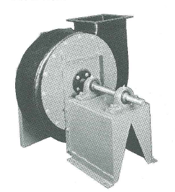
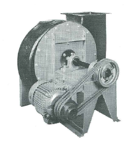
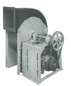
with specialized air engineering experience

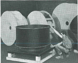
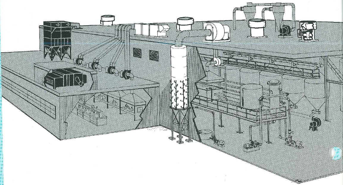
As can be seen from the typical chemical plant’ pictured here, has had years of experience in supplying all types of air handling equipment for operations involving corrosive materials. These units can be furnished also in steel, special metals and alloys or with a variety of coatings. The most economical and efficient selection is the standard by which air handling equipment will be recommended to assure you of extended satisfactory service at lower operating and maintenance costs.

INDUSTRIAL EXHAUSTERS VENTILATING FANS AXIAL FANS
POWER ROOF VENTILATORS PRESSURE BLOWERS AIR CLEANING EQUIPMENT


frp
FIBERGLASS

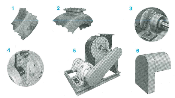
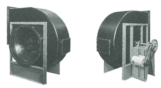
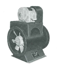
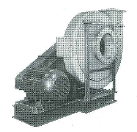
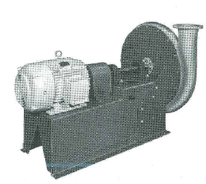
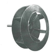
One-Piece solid FRP MW design wheel. Steel hub and shaft through the shaft seal are encapsulated with FRP.

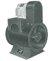
These fans are fabricated from FRP to extend service life under severe operating conditions . . . covering a broad range of corrosives. Housings are ratable and wheels are made of solid FRP except for the steel hub encapsulated in the wheel. The shaft, where exposed to gas stream, is FRP encapsulated through the shaft seal. All exterior steel parts are protected with a vinyl coating. Capacities from 300 to 85,000 CFM . . . static pressures to 20”. Ask for bulletin FRP 501A for additional information.

industrial exhausters

TYPE MW

ARRANGEMENT NUMBER 1

Featuring the Fiberglass Reinforced Plastic housing, type 316 stainless steel bolts imbedded and encapsulated in FRP housing for fastening inlet and drive side stands. Outlet flanges and inlet collar and flanges are solid FRP. Arrangement 1 is designed for belt or direct drive through a flexible coupling. All interior surfaces in contact with a gas stream are FRP. All exposed exterior surfaces are sandblasted, primed and multiple coated with a vinyl coating.

accessories

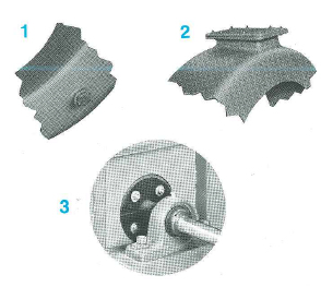
1. The standard drain connection is a threaded coupling type connected to the lowest point of the scroll to facilitate drainage of condensates or other liquids (standard). Flanged drains can be provided (optional).
2. For easy access to the wheel and housing, this FRP neoprene gasketed access door is quickly removed and replaced (optional).
3. Shaft seal of neoprene with FRP backup plate is bolted to the housing to limit gas leakage, but is not gas tight (standard).

4 FRP stuffing boxes and gasketed housing can be provided when standard shaft seal is not adequate (optional).
5 For large motor frames, a structural channel sub-base with integral motor slide base can be supplied in lieu of the standard Arr. 9 pivot base (optional).
6 Two piece, all weather hood protects motor, bearings and drive. Rear section can be tilted to inspect and check belt tension. Construction is vinyl coated steel, (optional on Arr. 10).


ARRANGEMENT NUMBER 9

Similar in features to Arrangement 1, this “package” unit features an adjustable motor mount. The steel pivot base assembly provides a rigid motor support and ease of belt tension adjustment which assures perfect sheave alignment.

ARRANGEMENT NUMBER 10

A “package” unit with a limited range of motor sizes, this unit is similar to Arrangement 1 with a variation of the motor mount used on Arrangement 9.


frp
FIBERGLASS

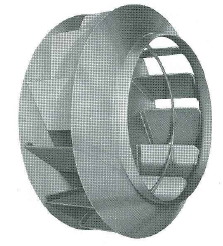
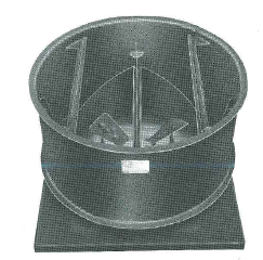
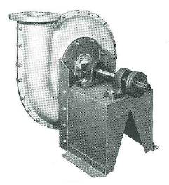
66” diameter design il “FRP”-FL rotor — all FRP with encapsulated steel hub.

In addition to the complete line of FRP MW Industrial Exhausters, “” “FRP”-FL non-overloading ventilating fans are now available.
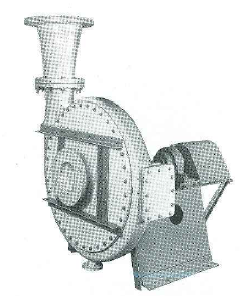
Housings are solid fiberglass reinforced plastic. Rotors are solid FRP except for the steel hub which is encapsulated in FRP. Shafts are encapsulated in FRP where exposed to the gas stream. Housing drain and neoprene shaft seal with FRP backup plate is provided as standard. The inlet and drive side bracing is attached to the FRP housing with type 316 stainless steel bolts which are encapsulated in the housing.
The housings are furnished with FRP flanged inlet and outlet for duct connection as standard. Housings are not reversible or rotatable. Discharges may be furnished in 45° increments only.
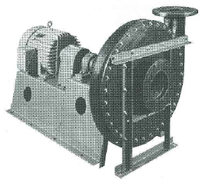
All exposed metal surfaces are sandblasted, primed and multiple coated with a vinyl protective coating. In addition to arrangement number 1 fans pictured, “FR P”-FL fans can be furnished in Arrangement number 9 with unistrut rails mounted on bearing base for motor and V-belt drive adjustment. For larger motor frames, a structural channel base can be furnished. Sixteen sizes are available with rotors from 12-1/4” to 73” in diameter to cover a wide range of capacities from 900 CFM to 129,000 CFM and static pressure to 6” W.G.

ventilating fans

TYPE FL

Arrangement No. 1 size 1320 ‘'FRP"-FL all FRP housing and rotor.

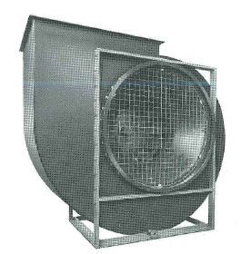
Arrangement No. 1 size 1320 “FRP”-FL design II fan — inlet side view with protective screen and flanged drain. 


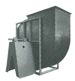
Arrangement No. 9 size 730 "FRP"-FL design II, with access door, adjustable motor side rails and shaft seal.

accessories

  1. The standard drain connection is a threaded coupling type connected to the lowest point of the scroll to facilitate drainage of condensates or other liquids (standard). Flanged drains can be provided (optional).
  2. For easy access to the wheel and housing, this FRP neoprene gasketed access door is quickly removed and replaced (optional).
  3. Shaft seal of neoprene with FRP backup plate is bolted to the housing to limit gas leakage, but is not gas tight (standard).


frp
FIBERGLASS

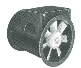
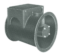
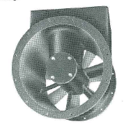
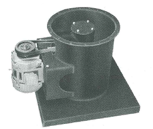
Lighter in weight and less costly than “special” metals, they afford a high degree of protection from corrosive fumes responsible for premature failure in metal, rubber lined and protective coated fans. They are ideal for horizontal or vertical installation in interior ductwork and require a minimum of space. Units are sparktested prior to shipment to assure complete corrosion protection. Capacities from 2000 CFM to 100,000 CFM . . . static pressures to 3”. Ask for bulletin F-305A for additional information.

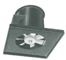
FRP Axial fan from entering air side. Durable predrilled inlet and outlet flanges are integrally molded into the housing.

FRP Axial Fan from discharge air side. The FRP inner cylinder and protective belt fairing are integrally molded to fan housing and sealed to protect shaft and bearings.

axial fans

EFFECTIVE SPACE SAVERS IN DUCT SYSTEM INSTALLATIONS WHERE CORROSION IS A PROBLEM

VANE AXIALS (FRPVA) have molded FRP curved discharge vanes bonded between the inner cylinder and outer casing for maximum fan efficiency, quiet operation and rugged construction

TUBE AXIALS (FRPTA) have extra thick FRP straight discharge vanes serving as struts between the inner cylinder and outer casing.

HOUSING — Solid Fiberglass Reinforced Plastic (FRP) construction with integrally bonded FRP flanges, protective belt fairing and inner bearing cylinder. Bearing cylinder has neoprene gasketed removable FRP end covers held in place with stainless steel bolts and nylon acorn nuts and easily removed for adjustment of fan sheave or bearing replacement.

STANDARD WHEELS — On all sizes from 15”through 36” the wheel is a one piece fiberglass reinforced molded epoxy wheel duplicating our cast aluminum type “MB” wheel. On sizes 42” through 60”, the basic wheel is a standard steel “MB” wheel encapsulated with FRP. The performance of these wheels is identical to standard Type “B” Axial Flow Fans.

ALTERNATE WHEELS — Design 80, 65 or 50 NV wheels have a cast malleable (15” through 42”) or cast steel (48” and 54”) spider encapsulated with FRP molded blades bolted and bonded to encapsulated spider can be furnished on all sizes.


SHAFTS are type 316 stainless steel with wheel end threaded for a stainless steel castle nut and cotter pin to hold wheel in place. The shaft and wheel have a keyway to prevent wheel from turning free. The castle nut is further protected with a molded epoxy acorn nut threaded on shaft and sealed in place to wheel hub with resin. The seal can easily be broken away by applying a pipe wrench to acorn nut for access to castle nut and wheel removal. After reassembly, this acorn nut can be resealed in place with resin in the field.

HAFT SEAL is neoprene with molded FRP backup plate held in place with stainless steel bolts and nylon acorn nuts.

BEARINGS - Two antifriction ball bearings completely enclosed within inner cylinder and having grease lines extended to grease fittings outside outer fan casing. These grease lines are completely protected within PVC enclosures from fumes being handled through fan.

MOTOR BASE is a vinyl coated external steel base supported in a rugged FRP support pivoted for belt tension adjustment.

Solid FRP support legs are integrally bonded to FRP housing and amply gusseted to support fan, motor and V-belt drive.

The protective belt guard shrouds the V-belt and motor sheave. A removable FRP coverplate and neoprene seal on end of inner cylinder facilitate access to fan sheave and bearing.

Internally molded cun/ed FRP guide vanes assure efficiency and quiet operation while providing rugged support of inner cylinder and belt fairing.


frp
FIBERGLASS

type of style v

The addition of a curb plate and style V damper head to an axial fan converts the assembly to an “AF” Type Style V Roof-Vent. Performance is identical to a standard steel AF Roof-Vent. Ask for bulletin RV-200 for additional information.
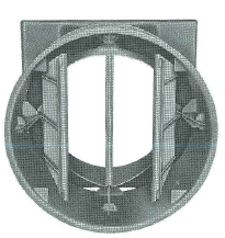
The damper head assembly complete with wind band and flanged stack is fabricated entirely of FIRP with butterfly damper blades pivoted on a stainless steel rod in Teflon bearings.

solow style v Roof-Vent

STANDARD WHEELS — Design 80, 65, or 50 NV wheels have a cast malleable (16” through 42”) or cast steel (48” and 54”) spider encapsulated with FRP molded blades bolted and bonded to the encapsulated spider are basically recommended. Performance of these wheels is identical to standard So-Low Style “V” “NV” Roof-Vents. SPECIAL CURBS — for peaked or sloped roof mounting can be furnished at extra cost. DISCHARGE STACKS — When it is deemed advisable to jet the fumes being discharged through a roofmounted unit at some elevation above the roof level, a discharge stack can be provided fabricated entirely of FRP for mounting on the Curb-Stack Assembly in lieu of the Damper Head Assembly. Gussets would be provided near discharge end of stack for attachment of guywire anchors which would be required. If desired, the discharge end can be necked down to provide a higher discharge velocity. Do NOT exceed 10 feet in stack height without checking factory.

Roof-Vent roof ventilators

TYPE AF and SO-LOW

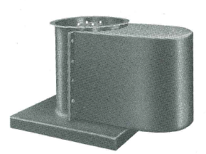
CURB-STACK ASSEMBLY - One-piece construction incorporates a rugged flanged roof curb sheet. A stream-lined venturi integrally molded in curb sheet closely shrouds fan wheel for minimum noise and maximum efficiency. The motor bracket assembly is rugged one-piece welded steel encapsulated with FRP. The ends of the support arms for motor bracket terminate in welded steel plates which are integrally molded into curb assembly.


Flanged curb plate is integrally bonded to housing and can be hard-furnished for flat, sloped or peaked roofs.

Weather cover (FRP) fastens in place with stainless steel ware and is easily removed for access to motor and drive.

DAMPER HEAD AND WIND BAND ASSEMBLY - fabricated entirely of FRP and with butterfly damperblades pivoted on a stainless steel rod in Teflon bearings. FRP damper stops molded inside wind band insure positive closing of dampers. Edges of damper blades flange over a V-trough rain gutter providing leakproof construction when damper is closed.


frp
FIBERGLASS

Size 65-4 FRP “CB” arrangement 9 with rubber lined rotor, common structural steel subbase, access door, drain and totally enclosed belt guard.

Size 40-3 FRP "CB" arrangement 1 arranged for direct connection through a flexible coupling, Titanium wheel with a Hastelloy C shaft, access door, drain, outlet cone and coupling guard.

Size FRP “CB" arrangement 8, Titanium wheel and shaft, coupling guard and carbon ring shaft seal (not pictured).

pressure blowers

TYPE FRP “CB” HIGH
PRESSURE BLOWERS

Type FRP “CB” high pressure blowers are furnished with a solid FRP housing. Steel bracing is attached to the FRP housing with type 316 stainless steel bolts encapsulated in FRP housing. Rotating assembly can be furnished in special metal or rubber lined for severe corrosive environments. All exposed external metal surfaces are sandblasted, primed and multiple coated with a vinyl protective coating. Static pressures to 100 inches W.G. plus and capacities to 50,000 CFM. Ask for bulletin FI-310 for additional information.

TYPE FRP “E” and “RE”
PRESSURE BLOWERS

Type FRP “E” and FRP “RE” pressure blowers are available, capacities to 3,300 CFM. Static pressures to 29” W.G. with FRP rotors, and up to 47” W.G. with special metal rotors. All housings are fiberglass reinforced plastic with a steel drive side plate. Drive side plate is attached to the FRP housing with type 316 stainless steel bolts encapsulated in FRP housing. All exterior metal surfaces are sandblasted, primed and multiple coated with a vinyl protective coating. Ask for bulletin FI-411 for additional information.

Size 4 FRP “RE" arrangement 8 with bearing base extended for direct connection of motor through a flexible coupling.

Size 6 FRP type "E” arrangement 1 for direct connection through flexible coupling or V-belt drive. Special feature includes an FRP stuffing box for prevention of gas leakage around the shaft.


frp
FIBERGLASS

corrosion tabulation

STANDARD RESINS OF CONSTRUCTION

*Polyester—Hetron 92 by Hooker Electrochemical Co. Atlac 382-05 by Atlas Chemical Division, ICI America, Inc. *Epoxy —by Bisonite Company, Inc. NOTE; Other Polyesters and Epoxies available upon request or as required where standard resins are not suitable.

physical properties

ASTM TEST METHOD
MINIMUM PROPERTIES

D-638 Tensile Strength, psi
12,000
D-790 Flexural Strength, psi
20,000
D-695 Compressive Strength, psi 20,000
D-790 Modulus of Elasticity in Flexural, psi
8x10^5
D-785 Hardness - Barcol
40

chemical resistance

Applications of corrosion engineering to air moving engineering is becoming more important daily in eliminating costly replacements, shut down time and fume control of many new and varied chemical processes. We have prepared a chemical resistance chart which we offer as a guide to plant engineers in evaluating our standard Fiber- glassresin equipment. These standards were selected for the widest possible range of chemical service commensurate with the best practice in mechanical constructions, design and economy.
NOTE: This guide is provided as a customer service and definitely should NOT be construed as any guarantee by the against damage due to corrosion, abrasion or erosion as per our standard terms of sale.
This guide chart also attempts to point out as many known limitations as possible, pertaining to standard construction. This does not mean however that is limited to these standards only, but can furnish special FRP fabrication upon request.
Test panels can readily be made available for test work in unusual applications and many plastic materials are available for special fabrication in a wide variety of Epoxy and Polyester-Fiberglass compounds.
We further wish to call attention to the fact that even though some chemical attack is evident on plastic materials under immersion conditions, application of this material may still give longer or more satisfactory service than conventional metals or coated equipment in contaminated air or gaseous conditions.
Two typical examples from field service are as follows:
1. It is well established that some chemical attack is evidenced on panels immersed in nitric acid and hydrofluoric acid concentrated at elevated temperatures; and yet plastic construction on exhaust hoods, fans and ducts over wash tanks containing these acids are still in excellent condition after three years service.
2. Certain chlorinated solvents will attack and decompose our standard resin materials on immersion and yet chloroform and methelene chloride fumes are exhausted in laboratory exhaust systems with years of satisfactory service.
Why use Fiberglass reinforced resin structures? Corrosion of metals produces a new chemical product of metallic salt or oxide which grows and deforms the metallic structure. Coating of metals gives a delaying effect to this corrosion which often extends the useful life of the equipment to satisfactory service. However, all plastic construction produces a solid plastic structure to eliminate all metallic corrosion. fans are carefully engineered to eliminate all metallic contact with the air stream which is essential for long life corrosion resistance.


Immersion Saturavad Vapor
Unsafurated Vapor or
Dust in Air Mixtures
Acids
Acetic, 5% S S S
Acetic, 10%
S S S*
Acetic Glacial
U U L*
Acetic Anhydride, Conc
U U L*
Aqua Regia (HN03-HCI) 3:1
U L S*
Benzene Sulfonic, Conc
s s s
Benzene Sulfonic, 25%
s s s
Benzoic, Conc
s s s
Boric s s s
Butyricm, Conc
s s s
Butyric, 25%
s s s
Carbonic s s s
Chloroacetic, Conc
U L S*
Chlorosulfonic Acid, 100%
U U L*
Chromic, 10%
S S S
Chromic, 50% S S S
Citric, all concentrations
S S S
Cresylic U U L*
Fatty, c^6 and up
S S S
Fluosilicic U S S
Formic 10%
S S S
Formic, 50% and above
U U S*
Formic,25% and above U S S*
Hyrdobromic, up to 50%
S U S
Hydrochloric, Conc
L S S
Hydrochloric, 10%
S S S
Hydrocyanic, all concentrations
S S S
Hypochlorous, 5%
S S S
Hydrofluoric, 40%
U L S*
HydroFluoric, 10%
U S S*
Lactic, all concentrations
S S S
Maleic, all concentrations
S S S
Nitric, 5%
S S S
Nitric, 10% S S S*
Nitric,20% S S S*
Nitric, 40% U L S*
Oleic, Conc.
S S S
Oxalic, all concentrations
S S S
Prechloric, up to 25%
NR NR S*+++
Phentol, above 10%
U S S*
Phosphoric, all concentrations
S S S
Picric 10%
NR NR S*+++
Picric 10% in alcohol
- - S*+++
Stearic, conc
S S S
Sulfuric, 3%
S S S
Sulfuric, 30% S S S
Sulfuric, 50% S S S
Sulfuric, 70%
L S S
Sulfuric, 93% U U L
H2SO4 - HNO3 Pickling Solution
S S S
Tartaric Acid, all conc
S S S
ACID SALTS


Alum. all conc
S S S
Ammonium Chloride, all conc
S S S
Ammonium Sulfate, all conc S S S
Copper Chloride, all conc
S S S
Copper sulfate, all conc
S S S
Ferric Chloride, all conc
S S S
Ferric Sulfate, all conc
S S S
Nickel Chloride, all conc
S S S
Nickel Nitrate
S S S
Nickel Sulfate, all conc
S S S
Stannic Chloride, 100%
S S S*
Stannous Chloride, all conc
S S S
Zinc Chloride, all conc
S S S
Zinc Sulfate, all conc
S S S
NATURAL SALTS
s s s
Barium Chloride, all conc
s s s
Calcium Chloride, all conc s s s
Calcium Sulfate, all conc s s s
Lithium Chloride
s s S
Magnesium Chloride, all conc
S S S
Magnesium Sulfate, all conc
S S S
Mercuric Chloride
S S S
Possadium Chloride, all conc
S S SS
Possadium Nitrate, all conc S S S
Possadium Sulfate, all conc S S S
Silver Nitrate
S S S
Sodium Chloride, all conc
S S S
Sodium Nitrate, all conc
S S S
Sodium Sulfate, all conc
S S S
Sodium Sulfate, 25%
L
L S*
ALKALNE SALTS
Sodium Bicarbonate 100%
s s s
Sodium Bicarbonate 10% s s s
Sodium Carbonate 2% s s s*
Sodium Chloride, Ph 11
u s s*
Sodium Cyanite
u l s*
Sodium Sulphide, 25% and above
s s s
Sodium Suphade, 10%
s s s
Trisodium Phosphate conc
l s s*
Trisodium Phosphat, 10% s s s*